liftmaster wire diagram
Contact Support. LiftMaster SL585UL and SL595UL Three Phase Wire Diagram.

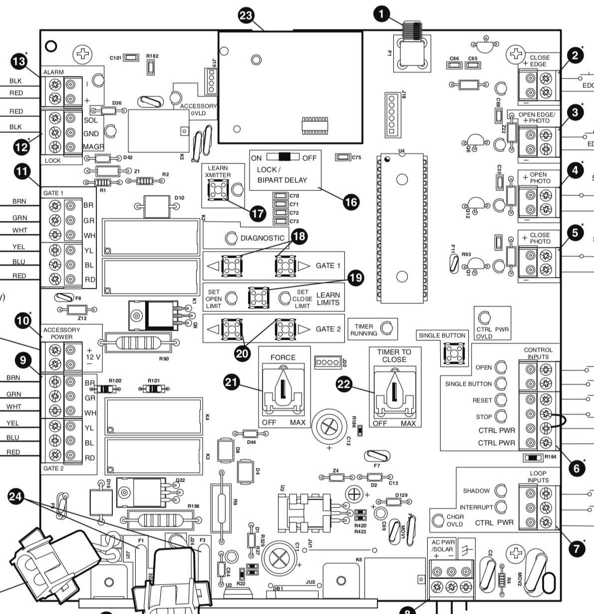
Liftmaster Boards Liftmaster Circuit Boards Liftmaster Control Board
For use on LiftMaster commercial door operators only.
. Direct connect commercial protector system for Logic Control. Chamberlain Liftmaster 412 receiver wiring diagram using video. LiftMaster CSW24UL Wire Diagram.
Wiring Diagram For Liftmaster. Single Phase Logic 50 Diagram. Provides protection for doors up to 30ft.
If it is manufactured in or later or if you are uncertain of the manufacture date you can determine compatibility by the color of the learn button near the wiring terminals. LiftMaster SL585UL and SL595UL Single Phase Wire Diagram. LiftMaster SL3000UL and CSW200UL Wire Diagram.
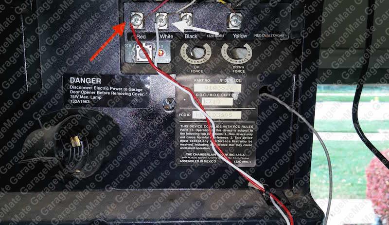
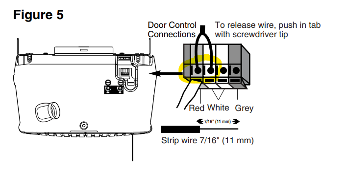
Loops are normally installed into slots cut in the roadway surface. Wiring Diagram Images Detail. Below is a description of where these wires go.
LiftMaster SL3000UL and CSW200UL Wire Diagram. To download the diagrams click the links below. The wiring for the stop circuit can be confusing.
Logic 50 Wiring Diagram. LiftMaster CSL24UL Wire Diagram. The AC 12hp motors have 3 wires 1 red 1 blue and 1 white wire that are not connected to either the high or the low voltage wire harness.
LiftMaster SL585UL and SL595UL Single Phase Wire Diagram. Contact Support. Contact Support.
LiftMaster CSL24UL Slide Gate Installation Manual. Chamberlain liftmaster professional 1 3 hp wiring diagram Wiring Diagram For Liftmaster Garage Door Opener And With The Door. The open and close buttons will wire in parallel to.
For instance if a module will be powered up and it also sends out a new. LiftMaster SL3000UL and CSW200UL Wire Diagram. Use a chalk line to mark the loop pattern and keep the rectangle parallel to the gate panel and the proper distance away.
Wiring garage door opener diagram liftmaster schematic sensor chamberlain craftsman wire lift doors master openers hp diagrams sensors sample safety. Effectively read a cabling diagram one provides to know how the particular components within the program operate. Wireless edge triggered more than 3 minutes Check wired input for wiring issue or obstruction.
Social Terms And Conditions. 69 Wireless edge triggered IF an. Below are diagrams that shows different methods for wiring multiple control stations.
LiftMaster LA500UL Wire Diagram. 68 Wireless edge loss of monitoring Check wireless edge inputs. Liftmaster hubs diagrams lift.
Nold
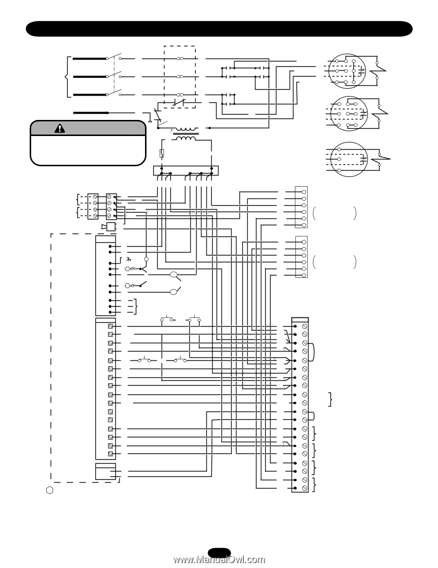
Three Phase Wiring Diagram Liftmaster Sl595 Sl595 Manual Page 31

Controlling Overhead Lights With A New Liftmaster Opener The Garage Journal

Chamberlain Liftmaster Circuit Board 41a5021 1h 315 For Model 1345 Or 1355 Openers
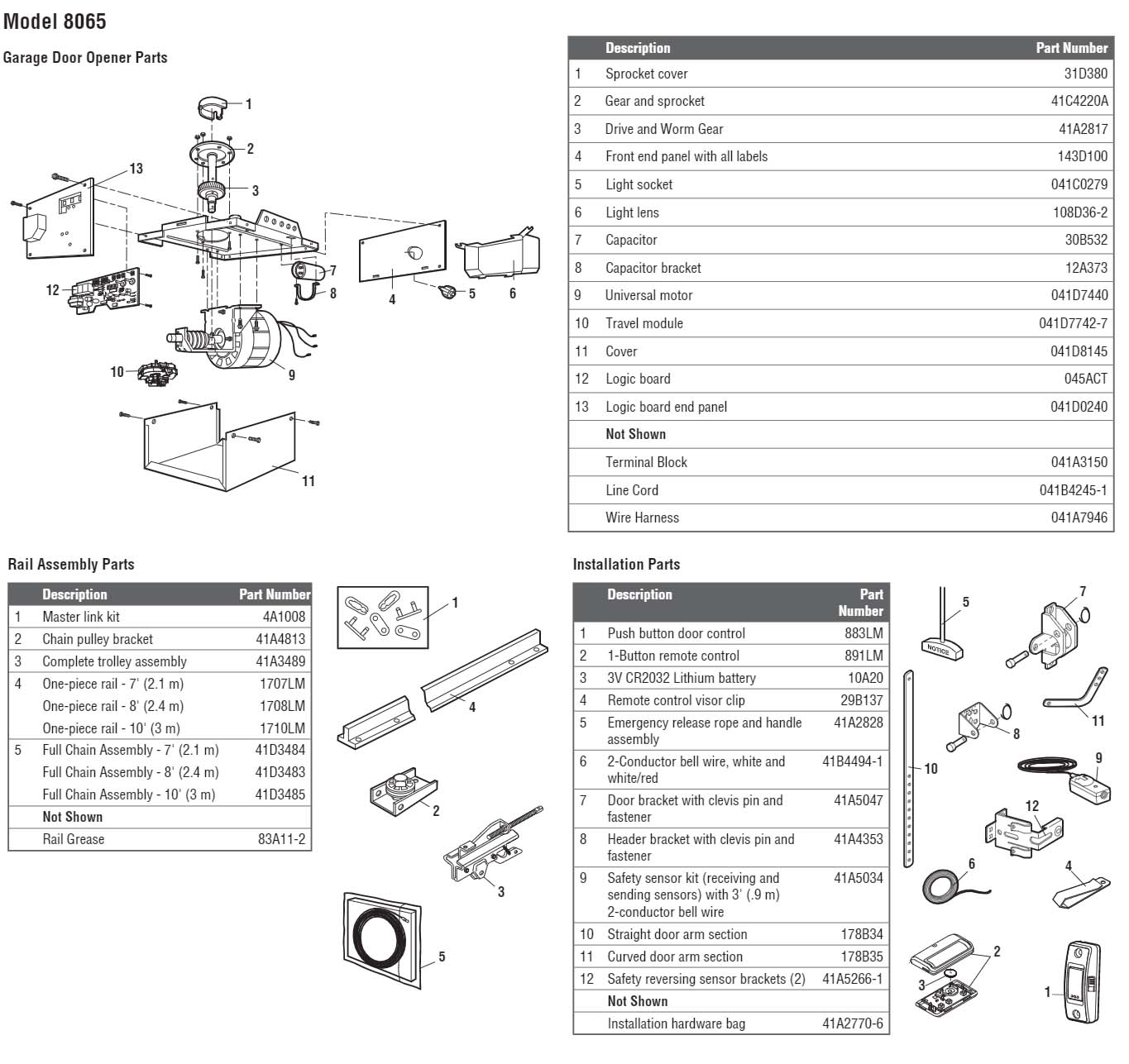
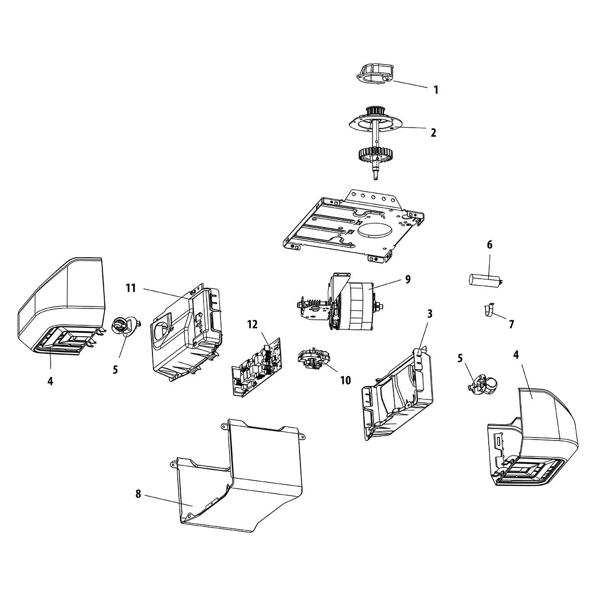
Liftmaster Parts Diagrams Parts Diagrams

Garage Door Opener Repair And Troubleshoting
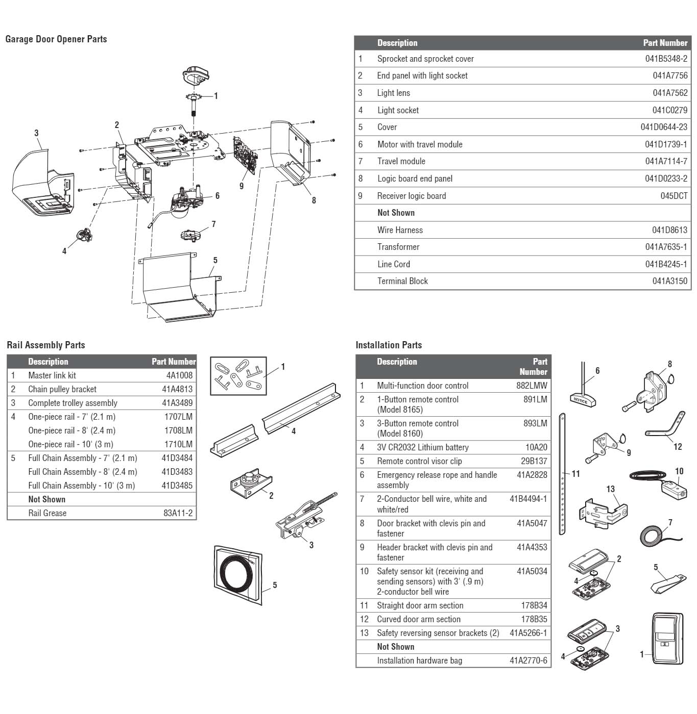
Liftmaster 8160 Garage Door Opener Parts Diagram And List Liftmaster Parts Diagrams Parts Diagrams
Garagemate Bluemate Labs Inc
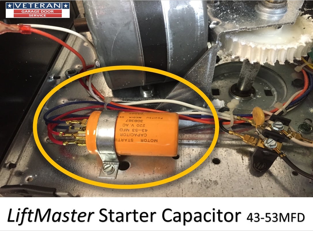
Replace The Starter Capacitor On A Garage Door Opener
Liftmaster 2280 Wiring Openers Garadget Community

How To Replace Your Drive Gears In Your Liftmaster Sears Craftsman Garage Door Opener

How To Wire A Garage Door Opener Chamberlain Myq Pt 2 Of 3 Youtube

Nold
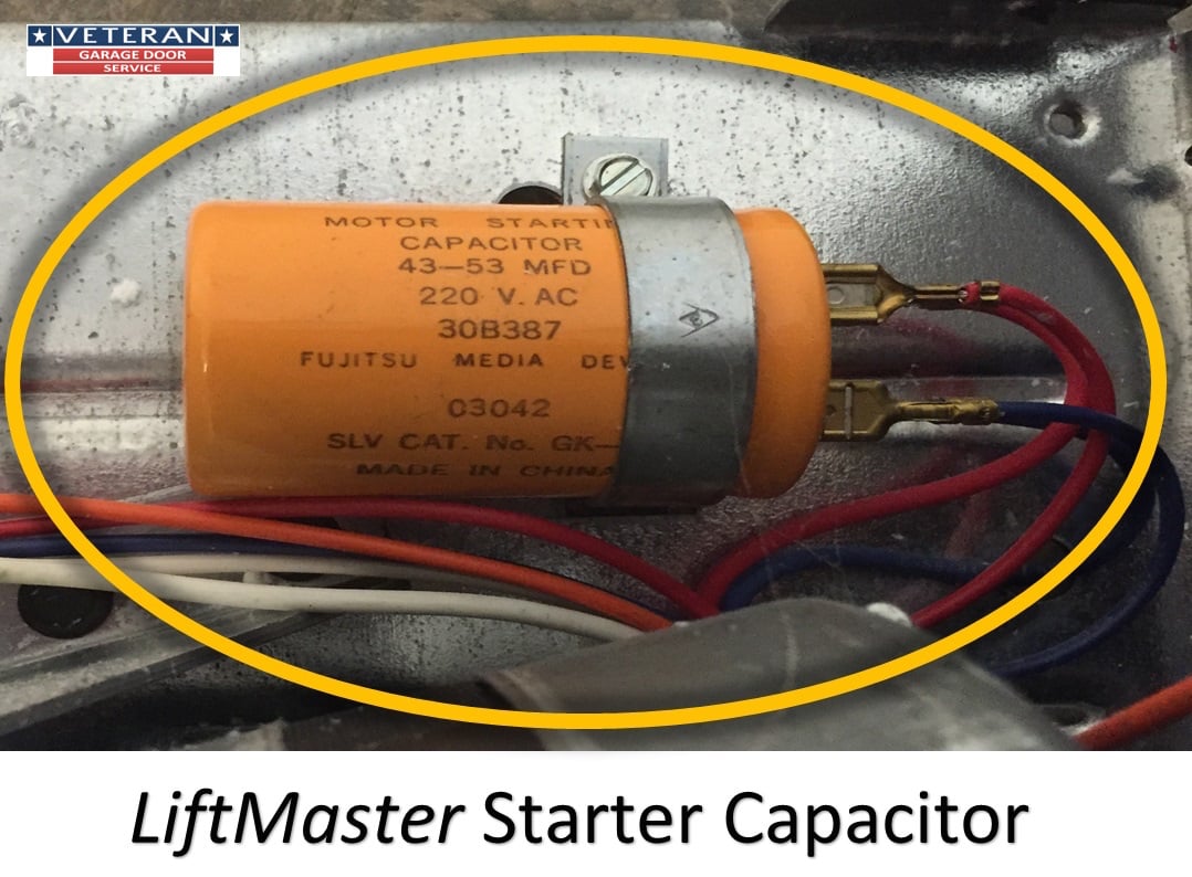
Replace The Starter Capacitor On A Garage Door Opener

Smart Garage Gate Opener For Liftmaster With Wifi Bluetooth Alexa Remootio

Unique Wiring Diagram Garage Door Morningculture Co Garage Door Sensor Garage Doors Chamberlain Garage Door
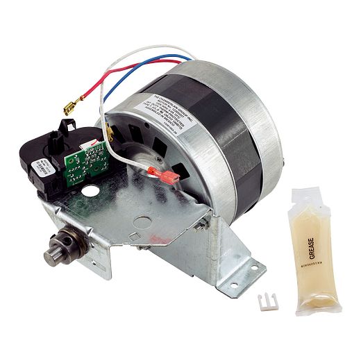
041d7440 1 2hp Motor With Travel Module Parts Liftmaster Canada